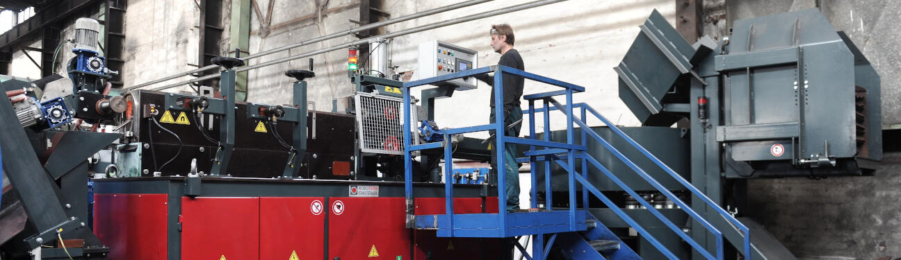
COMPLETE EQUIPMENT FOR INDUCTION HEATING


|
|
Heating parameters: |
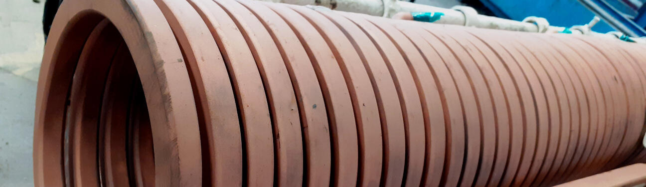
carbon steel 160 x 192 x 8 mm 272 x 40 mm 18 kHz 1 |
| Fig. 1 – Geometry |
Because the workpiece is heated for forming it must be heated homogenously. Using 3D simulation it is possible to find out where the most heat is generated and optimize the shape of the coil and the position of the workpiece to achieve the most homogenous heating. The Joule heat distribution is shown in Fig. 2 and Fig. 3. The red stripes correspond to the position of the coil turns because the regions closest to the coil conductor heat up more. The edge effect can be observed in the Joule heat distribution. The outer edges parallel to the current direction are overheated ant the outer edges perpendicular to the current direction are underheated. The electrical efficiency in the non-magnetic state is 63%.
 |
|
Fig. 2 – Joule heat – upper view |
 |
|
Fig. 3 – Joule heat – bottom view |