COMPLETE EQUIPMENT FOR INDUCTION HEATING


This paper was published in October 2020 in the Kovarenstvi magazine, issue 72, ISSN 1213-9289.
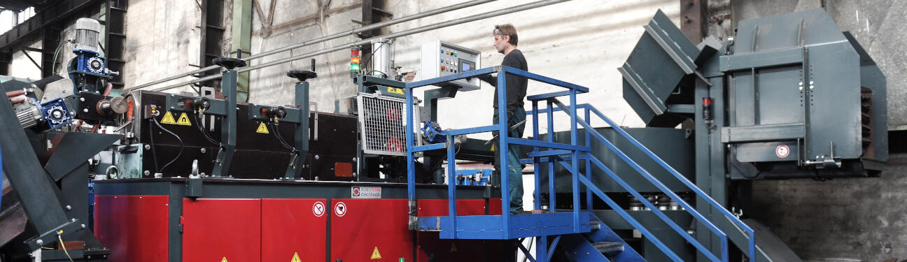
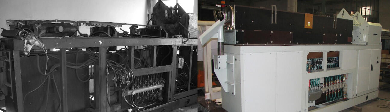
![]() Optimal induction heating process prior to forming
Optimal induction heating process prior to forming
The right choice of induction heater and the correct setting of the heating process are necessary conditions for achieving the best heating uniformity and maximum efficiency. The paper describes the causes of undesirable phenomena such as material overheating, excessive scale formation and billet sticking/welding. Recommended frequencies and heating times for the best quality of carbon steel heating are presented. Various continuous induction heating arrangements are described: single-stage heaters, multistage heaters, accelerated-heating inductors and short-coil inductors.
During induction heating energy is transported to the workpiece by an alternating electromagnetic field and heat is generated directly inside the workpiece. This is a great advantage of induction heating over indirect heating, where heat is transported by a temperature gradient. Everything around the workpiece heated by induction can be cold which results in low heat loss. Any electrically conductive materials can be heated by induction. Non-conductive materials can be heated by induction when placed in a conductive crucible. Induction heating of ferromagnetic materials is particularly advantageous because it achieves a very high efficiency. Induction can be used to heat solid conductors, liquid conductors and also plasma. Induction allows rapid in-depth heating which is especially advantageous in forge heaters. The possibility of easy mechanization and automation reduces the need for human labor. Thanks to its advantages the use of induction heating has been constantly growing in various branches of industry including forges where it has become an irreplaceable technology.
In order to achieve optimal in-depth heating and efficiency the frequency and heating time must be in the appropriate range. These parameters are closely related to the choice of heater, inductor, workpiece dimensions and cycle. In practice it happens unfortunately that the heater does not run in the optimal mode which is featured by reduced heating efficiency and other negative phenomena described below.
Because heat is generated directly inside the workpiece induction heating is more efficient than other heating technologies. Electrical and heat losses occur in induction heating. Electrical losses are caused by the passage of electric current and heat losses by radiation and convection of the workpiece or by heat dissipation to components that are in contact with the workpiece such as skid rails. Power source losses may include losses in the transformer, frequency converter, capacitors and supply busbars. The coil losses are significantly higher because the coil usually consists of a longer conductor and high current flows through it. Heat losses fundamentally affect the heating efficiency when the workpiece is heated to a high temperature which is common in heating process prior to forming.
 |
| Fig. 1 - Energy transformation of induction heating |
Power source losses in forge heaters are around 5% of the total power input and are only slightly dependent on the setting of the heating process and the properties of the selected inductor. If power source losses are not considered the total efficiency η of the heating process is defined as the product of the electrical efficiency ηe and thermal efficiency ηt.
(1)
Electrical efficiency indicates the ability to transfer energy from the inductor to the workpiece. It includes coil losses which depend on the shape of the coil and the proximity of the workpiece. Losses around the inductor (e.g. unwanted heating of surrounding components) can be neglected. Then the electrical efficiency is defined by the relation:
 (2)
(2)
Electrical efficiency can be calculated by computer simulation or in simple cases by mathematical formulas. For a long coil and a cylindrical workpiece the electrical efficiency can be approximately calculated from [1]:
(3)
where is:
D internal diameter of the coil [mm]
d workpiece diameter [mm]
δ1 coil skin depth [mm]
δ2 workpiece skin depth [mm]
ρ1 coil resistivity [µΩm]
ρ2 workpiece resistivity [µΩm]
µr workpiece relative permeability [-]
The generated heat is highest on the surface of the workpiece and decreases exponentially towards the core (so-called skin effect) [1-3]. 86.5% of the heat is generated in the skin depth δ which can be calculated from formula (4) or a practical online skin depth calculator on the ROBOTERM website can be used.
(3)
where is:
δ skin depth [mm]
f frequency [Hz]
ρ resistivity [µΩm]
µr relative permeability [-]
Electrical efficiency decreases with increasing D/d ratio because coupling of the inductor’s magnetic field to the workpiece is reduced. [1, 2] Therefore it is not appropriate to use a single inductor for a large range of workpiece diameters. The following figure illustrates the decrease in electrical efficiency when reducing workpiece diameter in a long inductor designed for a maximum diameter of 80 mm.
 |
| Fig. 2 - Electrical efficiency of heating cylindrical billets in a long coil with a diameter of 130 mm, carbon steel 1000°C |
The efficiency also decreases as the frequency decreases and the skin depth increases, as the electromagnetic transparency of the workpiece is more pronounced. This means that an electromagnetic wave passes through the material without absorbing energy [2]. The decrease in efficiency with increasing skin depth is shown in the following graph.
|
|
| Fig. 3 - Electrical efficiency depending on the ratio of skin depth to workpiece diameter, workpiece made of carbon steel 1000°C, workpiece diameter 80 mm, coil diameter 130 mm |
For forming and forging the workpiece should be heated as uniformly as possible. The low frequency deepens the skin depth and helps to heat up faster but reduces the electrical efficiency. High frequency prolongs the heating time and thus worsens the thermal efficiency. Therefore a frequency compromise is chosen to achieve sufficient temperature uniformity with good efficiency. The following economical range of workpiece sizes can be recommended for heating carbon steel to 1200°C:
| frequency [Hz] |
round workpiece diameter [mm] |
square workpiece size [mm] |
| 50 | 200 - 600 | 180 - 550 |
| 250 | 90 - 250 | 80 - 225 |
| 500 | 65 - 180 | 60 - 160 |
| 1000 | 50 - 140 | 45 - 125 |
| 2000 | 35 - 100 | 30 - 80 |
| 4000 | 22 - 65 | 20 - 60 |
| 8000 | 16 - 50 | 15 - 45 |
| 10000 | 15 - 40 | 14 - 35 |
| 20000 | 10 - 30 | 9 - 25 |
| Table 1 - Recommended frequency to heat magnetic steel | ||
Heat losses depend mainly on the workpiece temperature and heating time, less also on the thermal insulation of the inductor. For heating to low temperatures (approx. below 800°C) electrical losses in the coil have a greater proportion [1]. When heating to higher temperatures the radiation losses of the workpiece increasing with the fourth power of the thermodynamic temperature (Stefan-Boltzmann's law) are significantly manifested. Convection losses are negligible compared to radiation losses. With longer heating times to forging temperatures around 1200°C heat losses can significantly exceed the electrical losses in the coil.
The heated workpiece in the inductor radiates onto the refractory which heats up and radiates back onto the workpiece. It is therefore a mutual radiation in which mutual emissivity must be taken into account. The lost heat passes through the refractory and possibly through other insulating layers to the cooled coil where it is taken by cooling water together with the heat from electrical losses in the coil. Part of the heat is dissipated by skid rails which are in direct contact with the workpiece. Heat losses in the skid rails reach 2% to 8% [2].
The longer the workpiece is heated the greater the heat loss. Fig. 4 shows a possible decrease in thermal efficiency depending on the heating time. To achieve the best thermal efficiency the heating time must be minimized but it must be long enough to allow the core of the workpiece to heat up sufficiently.
 |
| Fig. 4 - Decrease in thermal efficiency with increasing heating time, carbon steel, final temperature 1250°C, workpiece diameter 60 mm, coil diameter 112 mm, mutual emissivity 0.7 |
The thermal efficiency can also be influenced by the thermal insulation properties of the inductor: the thickness of the refractory, the thermal conductivity of the refractory, the reflectivity of the refractory, or other insulating layers. The larger the diameter of the workpiece and the longer the heating time, the more important the thermal insulation is. Coils completely embedded in refractory concrete excel in their durability but allow better heat transfer from the refractory concrete to the coil. The lower the thermal conductivity of refractory concrete the worse its strength (porosity increases). A trade-off must be made between the thermal insulation and mechanical properties of the inductor.
Thermal insulation can be improved by increasing the thickness of the refractory. However this increases the coil diameter and decreases the electrical efficiency. When heating a workpiece with a diameter of less than about 55 mm the heating times are short and electrical efficiency is more important so it is advisable to minimize the refractory thickness and coil diameter to values that still ensure sufficient inductor lifetime because too thin refractory shortens the lifetime. For larger diameters the importance of thermal insulation increases and there is an optimum coil diameter but the total efficiency of the inductor is only a little sensitive to changes in coil diameter as changes in thermal and electrical efficiency compensate for each other. In general when heating to forging temperatures the heating time has a greater effect on the total efficiency than the coil diameter.
 |
| Fig. 5 - Thermal efficiency depending on coil diameter for different heating times, carbon steel, final temperature 1250°C, workpiece diameter 100 mm |
The uniformity of final temperature is one of the main criteria for evaluating the quality of heating in forges. The temperature of the heated workpiece is in practice measured contactless by pyrometer. However the surface temperature tells little about the quality of the heating. The measurement of the temperature inside the workpiece is very complicated therefore it is very advantageous to use computer simulation which calculates the entire time development of the core-surface temperature profile.
Due to the skin effect the heat is generated more at the surface of the workpiece and reaches the core by conduction. The skin depth at which most heat is generated depends on the frequency. High frequencies cause a low skin depth and extend the required heating time. Low frequencies deepen the skin depth and shorten the heating time. Too low frequencies cause transparency and reduce heating efficiency. Sufficient heating time should be chosen to heat up the core well. However, too long a time leads to low efficiency, greater scale formation and subsurface overheating. [3, 4].
A typical temperature development during single-stage continuous heating of carbon steel is shown in Fig. 6. Magnetic steel has a very low skin depth at the start of heating and the thin surface layer heats up very quickly to 800°C where it loses its magnetic properties and the skin depth increases. This is followed by a slow increase in surface temperature. Electromagnetic waves penetrate more deeply and a lot of energy is consumed for crystal structure changes. After overcoming phase changes the surface temperature rises faster. Towards the end of the heating, radiation losses gain significantly. The surface heats up more slowly and the temperature maximum moves below the surface of the workpiece. The core-surface temperature difference decreases. After the heating is finished the surface is naturally cooled and the temperature maximum moves to the core.
 |
| Fig. 6 – Temperature development during heating round magnetic steel, diameter 80 mm |
Fig. 7 shows how the heating time affects the final temperature distribution of 60 mm round steel billet when the surface is heated to 1200°C. In short heating times the core is colder than the surface, in long heating times it is vice versa. The temperature maximum occurs below the surface due to large radiation heat losses. The transport of the hot billet to the forming machine usually takes a few seconds. During this while the surface cools down quickly. The dashed curves show the temperature after 8 seconds of natural cooling. If cooling is considered a shorter heating time in this case leads to better temperature uniformity.
 |
| Fig. 7 – Final temperature profile, round steel billet, diameter 60 mm, frequency 2000 Hz |
At an optimum heating time the surface should be several tens of degrees warmer than the core at the end of heating. After the heating is finished the surface cools rapidly due to radiation and the core-surface temperature difference can inverse within a few seconds. Too short heating time causes an under-heated core which increases the deformation resistance and wear of the die. In practice is more often used too long heating time which has following severe disadvantages [3, 4]:
Long heating time together with a high target temperature increases the risk of material overheating or burning below the surface. The temperature below the surface can be up to several tens of degrees higher than the pyrometer shows. In the case of metallurgical burning intergranular melting occurs, which irreversibly worsens the mechanical properties (ductility, strength). Overheating and burning can also occur during forming when the temperature increases further from deformation.
Long heating time causes decarburization, internal oxidation and increased scale formation. Scale formation is associated with loss of metal and energy. Scales cause dimensional inaccuracy, clogging of device, reduced life of forming and cutting tools. Due to scale the pyrometer cannot measure the temperature correctly which impairs the stabilization of the heating process. Scales have a negative effect on the inductor's durability. The wear of the skid rails increases. Scale dust penetrates into the refractory micro-cracks and accelerates their enlargement resulting in a short circuit.
Heat losses during heating to forging temperatures around 1200°C greatly affect the total heating efficiency. The longer the heating time, the more energy is emitted by the surface. Excessive heating time can reduce efficiency by several tens of percent.
Undesirable sticking/fusing/welding of the billets occurs due to the high temperature in combination with the pressure from the feed mechanism [4]. The longer the heating time is the higher is the maximum temperature below the surface. The pressure between the billets in the inductor decreases with the distance from the feed mechanism. If the heating time is long high temperatures are reached at the beginning of the inductor where the pressure between the billets is highest.
The recommended minimum heating times for heating round magnetic steel to a forging temperature of around 1200°C are given in the following table. For a square cross section the time must be multiplied 1.25 times, for a slab 2 times. The heating times were calculated for in-line continuous constant power heating where in the final state the surface is 50 degrees warmer than the core. Double this time can be considered acceptable. At longer heating times it is advisable to consider measures that could shorten the heating time: shortening the cycle, increasing the frequency, using an inductor with shorter coil, using a lower power heater with a shorter inductor.
| diameter | frequency | time | frequency | time | frequency | time |
| 20 mm | 4000 Hz | 18 s | 10000 Hz | 22 s | 20000 Hz | 27 s |
| 30 mm | 3000 Hz | 40 s | 4000 Hz | 44 s | 6000 Hz | 49 s |
| 40 mm | 2500 Hz | 73 s | 3000 Hz | 77 s | 5000 Hz | 90 s |
| 50 mm | 1500 Hz | 103 s | 2500 Hz | 120 s | 4000 Hz | 138 s |
| 60 mm | 1000 Hz | 135 s | 2000 Hz | 167 s | 3000 Hz | 189 s |
| 70 mm | 1000 Hz | 189 s | 1500 Hz | 215 s | 2000 Hz | 235 s |
| 80 mm | 800 Hz | 235 s | 1000 Hz | 252 s | 1500 Hz | 286 s |
| 90 mm | 700 Hz | 292 s | 1000 Hz | 325 s | 1500 Hz | 370 s |
| 100 mm | 700 Hz | 365 s | 1000 Hz | 410 s | 1500 Hz | 460 s |
| 120 mm | 500 Hz | 485 s | 700 Hz | 540 s | 1000 Hz | 600 s |
| 140 mm | 500 Hz | 675 s | 700 Hz | 745 s | 1000 Hz | 820 s |
| 160 mm | 300 Hz | 762 s | 500 Hz | 895 s | 800 Hz | 1020 s |
| 200 mm | 200 Hz | 1100 s | 300 Hz | 1250 s | 500 Hz | 1440 s |
| 300 mm | 150 Hz | 2380 s | 300 Hz | 2870 s | 500 Hz | 3200 s |
| Table 2 - Recommended minimum heating time of round shape magnetic steel | ||||||
In the case of a continuous single-stage heater with a constant longitudinal power distribution the heating time depends on the cycle and the length of the billet according to the following relationship:
 (5)
(5)
If the billet length and the cycle are determined by forging technology, the required heating time can only be achieved by changing the coil length. This must be taken into account when choosing or designing an inductor. Another solution is to use a multi-stage heater, which allows the power to be distributed unevenly along the heating line [3-5].
The forge heats carbon steel billets on a single-stage continuous heater with the following heating parameters:
According to relation (5) the actual heating time is 442 s. The recommended heating time (Table 2) is exceeded approximately eight times, which indicates poor thermal efficiency. The frequency of 2050 Hz is at the lower limit of the recommended range (Table 1). From the relation (4) the skin depth δ for the non-magnetic state is 12.3 mm. The δ/d ratio is 3.4. This indicates reduced electrical efficiency (Fig. 3). A higher frequency would be more suitable because with such a long heating time only a small skin depth is sufficient for heating.
Computer simulation provides more detailed information. For this case, the total heating efficiency is only 31%. In addition it is revealed that the temperature maximum at the end of heating occurs in the center of the billet and exceeds the surface temperature by 36°C. There is a significant overheating of the core.
The primary reason for the reduced efficiency and quality of heating is an inappropriately chosen heater and inductor which are designed for much higher power rate. Excessive heating time can be reduced by using a short coil inductor. If the coil is only 1 m long, i.e. one third of the original length, the heating time is reduced 3 times and the total efficiency according to the simulation increases to 53% which corresponds to a saving of 63 kW. The heating parameters can be fully optimized by using a special inductor and heater. According to the simulation a total efficiency of 66% corresponding to a saving of 81 kW can be achieved by further shortening the heating time, increasing the frequency and reducing the coil diameter. Other benefits will be better temperature uniformity, less scale formation and a higher power factor.
The ROBOTERM company offers various solutions for heating optimization. Their purpose is that the power is distributed unevenly along the heating line. These solutions include multistage heaters (Fig. 9), inductors for accelerated heating (Fig. 10) and inductors with a shortened coil (Fig. 11).
 |
 |
| Fig. 8 - Standard inductor | Fig. 9 - Double stage heating |
 |
 |
| Fig. 10 - Accelerated-heating inductor | Fig. 11 - Short-coil inductor |
Multistage heaters have two or more inductors with separate power sources. This allows the power to be distributed arbitrarily along the heating line. It is possible to change the cycle while maintaining the optimal final core-surface temperature profile. At low power rates only the last inductor heats. At high power rates the first inductor heats to full power and the other inductors only maintain the surface temperature while the heat is distributed to the core. Multi-stage heaters are advantageous where a large power range is required.
Short-coil inductors and accelerated-heating inductors can be used on single-stage heaters which are widespread for their simplicity and low cost. The advantage is the quick replacement of the inductor, especially on heaters with transversely displaceable inductors which can be replaced completely automatically. The coil length can be designed for the optimal heating time and required power.
Short-coil inductors can solve the problem of too long a heating time on a single-stage heater. Their advantage is also that when heating in a short coil there is usually no decrease in the power factor as when heating with reduced power in a standard inductor. However, the length of the coil should be many times greater than the billet length otherwise the temperature unevenness in the longitudinal direction increases.
Accelerated-heating inductors have a coil with unevenly distributed threads. The highest thread density is at the beginning of the inductor which allows minimizing the required heating time. Accelerated heating inductors can solve the problem of cold core of the billets and allow reducing the cycle compared to heating in a standard inductor. The disadvantage of the accelerated-heating inductor is the large amount of underheated billets when starting the heater with a full inductor. Rapid heating is not suitable for brittle and poorly conductive materials (e.g. high carbon steels) as a high temperature gradient at the beginning of heating can cause them to crack.
The heating time and the power distribution along the heating line fundamentally affect the quality and efficiency of the heating. Optimal heating can be achieved with a multi-stage heater or with a single-stage heater if its inductor is specially designed for the required power. The recommended heating times can be used both in the design of a new heating line and to evaluate the quality of the heating process on single-stage heaters in forges. Replacing an inductor or an entire heater can in some cases bring significant energy savings, increase heating quality and equipment life.
Literatura:
[1] Rudnev, V.; Loveless, D.; Cook, R.; Black, M.: Handbook of induction heating, 2003, ISBN 0824708482
[2] Šmejkal, M.: Optimální postup při indukčním ohřevu. Kovárenství. 2007, č. 30, s. 12-15. ISSN 1213-9829.
[3] Rudnev, V.; Brown, D.; Van Tyne, Ch.; Clarke, K.: Intricacies for the successful induction heating of steels for modern forge shop. Proc. of the 19th Int'l Forging Congress, Chicago, IL, September 2008
[4] Rudnev, V.: Induction heating of steel billets: causes of billet sticking/fusing problem and its prevention, in heat processing 4, 2019, p. 57-60
[5] E. Rapoport, Y. Pleshivtseva, "Optimal Control of Induction Heating Processes", 2006, ISBN 9780849337543